This is the third article in a three-part series considering the challenges PFAS (per or poly fluorinated alkyl substances) present to the environment and potential solutions.
Most short-term acute generation of PFAS is from the use of AFFF (aqueous fluorinated firefighting foam) in firefighting exercises and responses. More chronic and gradual long-term generation occurs from decomposition of polymeric fluoropolymers like Teflon, leaching of fluorinated additives like surfactants and plasticizers, and release of fluorinated industrial solvents.
PFAS contamination of soil and groundwater is from a number of sources such as the use of PFAS firefighting foams, landfill leachate, waste water treatment plants and manufacture of PFAS. Most of the soil and groundwater contamination currently been investigated is due to use of PFAS firefighting foams in particular during training. As a result virtually all of those soil and groundwater PFAS contamination is in the presence of residual hydrocarbon, a result of fire training wherein hydrocarbon (gasoline, diesel or aviation turbine fuel) was used as the fuel source. In the US regulators are now looking into more and more PFAS contamination of rivers, from which drinking water is drawn. The source of the PFAS contamination is often from the manufacture of PFASs, the types and concentration of PFASs detected in the rivers are not used in making firefighting foams but for other products such as fluoropolymers.
The Aqueous Fluorinated Firefighting Foam (AFFF), when applied to a fire, forms a foam blanket above the surface water. Of particular interest, an oil emulsion in the water, resulting from the AFFF mixing with residual fuel source, which may be any combination of, for example, oil, petrol, JetA1, Avtur, etc. The fuel/water/AFFF emulsion is very stable and does not phase separate, even if allowed to stand in a holding pond for an extended period of weeks. Thus, treatment of the contaminated water must allow for, and be capable of, treating free oil and hydrocarbons, emulsified and soluble oil, and then, finally, PFAS.
The purpose of using fluorosurfactants the PFAS firefighting foams is to reduce the water/oil interface surface tension so that the foam can flow easily and increase foam penetration.
Current treatment methods
PFAS contaminated water is most commonly treated by adsorption through the use granular activated carbon (GAC) and/or ion exchange (IX) resins. Such an approach is advantageous due to the low cost of deployment and ease of set up at point of entry.
Regeneration of absorbent media such as Ion Exchange Resin, whilst attractive for increasing service life, also has a downside as the concentrated PFAS waste brine solution must then be contained and transported to a suitably qualified waste treatment site for PFAS.
The adsorption media most commonly applied today for PFAS removal was not designed for such specific use; hence, media is readily subjected to fouling, which greatly reduces efficiency. Drawbacks of such an approach include inefficiency (frequent replacement required), limited range (often requires combination with additional treatment option such as reverse osmosis), and different size PFAS chains vary with respect to water solubility (smaller chains are more water soluble, thus, less affinity for binding agents).
The use of adsorbents in PFAS remediation is problematic because PFASs easily desorb in the presence of other organic compounds with higher affinity for the adsorbent. Due to the low tendency of PFAS to undergo usual weak attractions (i.e., van der Waals forces), they are easily displaced by other organic impurities which may be present. This results in a very unfavorable adsorption/desorption isotherm, requiring the use of large amounts of adsorbent in the absence of effective pre-filtration.
Another downside to deployment of adsorption media is the abundant generation of waste both sludge and solid. Such solid waste is typically treated via combustion (it’s important to ensure complete destruction, which often requires temperatures above 1200 C), sludge is a more difficult and costly waste item to transport and then treat.
Regeneration of absorbent media such as Ion Exchange Resin, whilst attractive for increasing service life, also has a downside as the concentrated PFAS waste brine solution must then be contained and transported to a suitably qualified waste treatment site for PFAS.
MyCelx filtering media cartridges are hydrophobic, after filtering PFAS from the water the cartridges are safely handled, stored and transported as a dry waste, preferably disposed of by thermal destruction (small volume with proportionally low cost) with no lingering or contingent liability often associated with burial.
The search for an in-situ approach is ongoing. Researchers have demonstrated generation of hydroxyl radicals, as well as persulfate radicals in water can be employed to destroy longer-chain PFAS. The problem is incomplete destruction leading to smaller, shorter-chain PFAS daughter products.
PFAS does offer some specific characteristics that can be taken advantage of, in theory. By taking advantage of chemical properties such as partial positive charges on Carbon atoms along with partial negative charges on Fluorine atoms, nucleophilic reactions offer promising potential. In fact, hydroperoxide and superoxide radicals have been shown to destroy PFOA with no detectable shorter-chain PFAS; however, the problem becomes the slow rate of reaction, which is typical of a nucleophile reaction.
Additional technologies that have been considered include use of an enhanced contact plasma reactor, high temperature/high pressure, and bioremediation. Complete destruction via an enhanced contact plasma reactor has been demonstrated effective on a small scale (tested in 2019 at Wright Patterson AFB).
The downside to plasma is the sheer amount of energy required to scale such technology. Prior work was demonstrated effective for treatment of a small number of gallons over a 48-hour period. High temperatures and pressures have also been demonstrated effective for destruction of PFAS, however, such solutions are not cost effective.
The conclusion of this case showed that on-site treatment was possible with small footprint MyCelx plant within the OLEOLOGY container, lower cost and discharge that consistently was below the water utility’s requirement for discharge to sewer.
Bioremediation is unlikely to be a feasible approach because of the bond energy associated with the carbon fluorine bond, which exceeds the energy available even from known coupled enzyme-mediated reactions in cells.
An alternative emerges
Conventional water treatment plants that rely upon use of GAC and IX resin, incorporated for removal of PFAS, cope only for a short period of water treatment before breakthrough occurs. The residual hydrocarbon in the groundwater quickly overloads the GAC, saturates and breaks through the GAC and IX, leading to premature failure of the PFAS water polishing.
Some in-field operational cases where problems were identified after the installation of the PFAS upgrade equipment are highlighted in the cases below:
- Wastewater collection and treatment company – collects water from industrial waste, leachate from refuse dumps and fire training water. Water collected is treated at a central wastewater treatment plant. Treated water is discharged to sewer under license conditions set by the regional water utility.The treated wastewater to sewer discharge criteria originally allowed for 30 ppm O&G (oil and grease) discharge, dissolved metals and various other contaminants BOD (biochemical oxygen demand) and COD (chemical oxygen demand) all in mg/L (part per million) were acceptable for discharge to sewer.The water utility, aware of PFAS contaminants being discharged by some industry sectors, added further license conditions for discharge to sewer. The license change increased the range of water analyses for discharge to sewer to include PFAS with maximum allowed discharge limits set as parts per trillion (ppt), for PFOS, PFHxS, PFOA, however for O&G the limit remained at 30 ppm maximum. The dilemma was about to be discovered, as ppm vs. ppt, the huge difference between contaminant levels previously generally compliant when measured in ppm and the new PFAS ultra-low levels (ppt) required a complete mindset change in design of the treatment system.The underlying issue is quite significant; in order to achieve the PFAS removal to compliant levels of parts per trillion, the hydrocarbons remaining in the water must also be removed by the absorbent media, either before the final polishing stage or at the final polishing stage. The hydrocarbons will also be removed to the same relative level of ppt, and thus any absorbent polishing system added, must be designed to cope with the additional hydrocarbon contaminant load and spikes, in addition to capability and capacity to treat for PFAS, before break through occurs.The utility’s requirement for compliant oil & grease discharge to sewer may be set at 30 ppm, but in reality the water treatment and polishing system must remove the oil & grease to ultra-low levels of ppt similar to that of PFAS. As and when, the regional water utility’s implement such regulations, this will be a very significant change for discharge to sewer for the wastewater treatment.
The wastewater treatment company added a polisher skid with granular activated carbon (GAC) and ion exchange resin (IX) as a final stage to the existing water treatment plant.
The GAC and IX were added to target the removal of the PFAS. GAC, however, is not specific in contaminant removal, to the contrary it will generally remove any and all contaminants in the water in a hierarchy of affinity, to the point of saturation. GAC quickly saturates and “breaks through” in the presence of spikes of O&G and oily emulsions. Once the GAC saturated, the following polisher of IX experiences an immediate negative impact due to hydrocarbons and emulsions rendering both GAC & IX to waste. The $1M+ spent on the polisher did not achieve the outcome sought, after treating less than 10,000 gal. of water, discharge was noncompliant, and discharge was halted.
The resulting conclusion from this case is that, to consistently achieve ultra-low level compliance at discharge, the water treatment plant requires robust pre-treatment for pre-filtering and polishing, or risk early breakthrough and saturation at the polishing stage, increasing changeout and waste removal and non-compliant discharge.
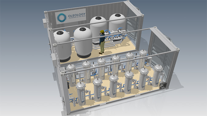
- Metal reclaimer – Firefighting water with AFFF to be treated after fire event at metal reclamation facility.A fire at a metal reclamation company caused the foam system to blanket the fire and yard with AFFF foam to extinguish the fire.The company collected the foam and water with residual hydrocarbon (fuel & oil) and stored the water in tankage at the site, seeking a suitable, and viable, removal or treatment with discharge approval to sewer.Options were reviewed by the client, including truck away, mobile systems with GAC & IX and also OLEOLOGY mobile plant with MyCelx technology.OLEOLOGY has developed a water treatment plant that incorporates MyCelx patented filtering. The fixed chemistry of the MyCelx technology is robust, has affinity for hydrocarbons, O&G and PFAS. The benefit of the MyCelx fixed chemistry and affinity for both O&G and PFAS is that the varying levels of contaminant are sequentially reduced by a series of filtering stages prior to the final polishing. The MyCelx-infused filter sequence, gradually, sequentially reduces the contaminant load, so that the water, after filtering through all primary MyCelx stages, is a homogenous mix of water and only low levels of both O&G and PFAS at the inlet to the MyCelx final polisher stage. This is unique and was first utilized at a fire training ground in 2006 to decontaminate AFFF, Kerosene (Jet fuel) residue and water, which had formed a very stable oily emulsion.
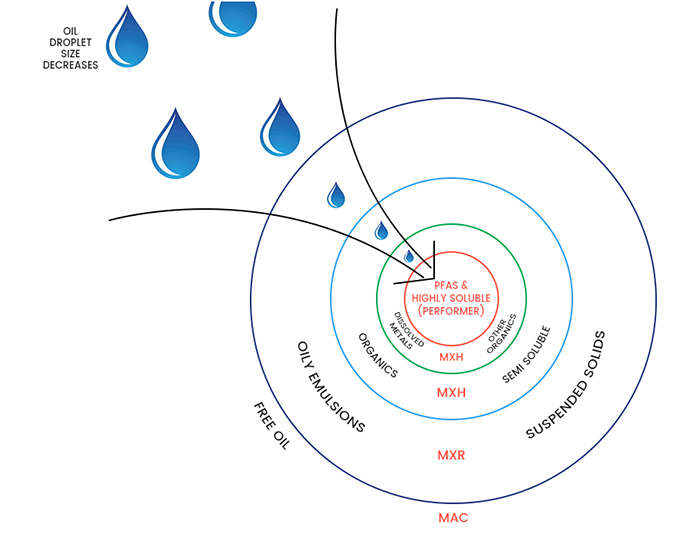
OLEOLOGY employs the “onion” analogy to describe the process; in order to get to the PFAS contaminants, which are the smallest volume in the centre of the onion, the larger outer layers of the onion must be sequentially removed.
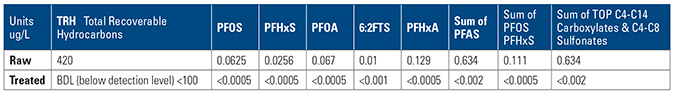
The company chose OLEOLOGY containerized plant with MyCelx filtering and MyCelx polishing, and made a submission to the water utility to discharge at <0.0005 ug/L (or <0.5ppt).
The system selected for treatment of the water required a robust method to remove suspended solids of an oily nature, emulsified oily water with foam/surfactants and high levels of dissolved metals and carbon.
Truck away and treat was an impediment to site operations and, also was not viable at a price point of $4.00 per gal. The solution was to employ a container system to treat and discharge at site. The regulator commended the discharge quality of the water and cost including mobilization, hire, treatment, waste and demobilisation was less than 10 cents/gal.
The conclusion of this case showed that on-site treatment was possible with small footprint MyCelx plant within the OLEOLOGY container, lower cost and discharge that consistently was below the water utility’s requirement for discharge to sewer.
- Firefighting training facility – ground water with AFFF contaminationClient required water from a fire-training ground to be PFAS free. The new training foam (fluorine free foam) was in use, however leaching PFAS from the old fire-training pad continues with use.
The fire-training ground is used for a variety of training scenarios, each scenario may require differing fuel type as the fire source, resulting in water/oil/foam for treatment varying significantly.
The evaluation specification included assessment of type of water treatment plant for removal of PFAS and hydrocarbon factors, such as footprint, energy consumption, operation cost, waste (volume of dry and wet waste generated) and cost to treat and servicing required for the new plant.
Technology Contenders were GAC, IX and OLEOLOGY with MyCelx.
Based on the footprint, OpEx, CAPEx, robust & systematic water treatment with reduction of contaminants and low waste, MyCelx was chosen.
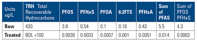
The system is operating at 15,000 gpd treating water to 1/10 below level specified by the client.


