Many chemical and pharmaceutical manufacturing processes involve reactions of solid and liquid-phase reactants to produce a slurry. The slurry typically needs to be separated into its component parts — the liquid (i.e., mother liquor) and the solid. The valuable material may be the liquid, the solid or both phases. The component to be recovered determines the type of separation method and equipment used. For example, if the liquid is the desired product, the solids are removed as waste to produce a clean liquid; if the solid is the desired product, recovery of small particles increases the product yield.
Generally, the first step after the reaction is a bulk separation process that removes large, coarse solids (larger than 5 μm). Bulk separation can be by vacuum filtration (belt filter, nutsche filter or drum filter), pressure filtration (filter-dryer, rotary pressure filter) or centrifugation. But as processes have become more sophisticated and quality requirements have tightened, it has become necessary to remove residual particle fines from slurries. These particles are small — typically 1–5 μm in diameter, or even smaller — and at low concentrations, on the order of parts per million (ppm).
A clarification system is employed after coarse-particle filtration or as a stand-alone system to remove or recover fine particles at low concentrations. The typical approach for fines removal/recovery has been bag filters, cartridge filters, manual plate filters and filter presses. A new approach is the use of automated, pressure-filtration, clarification technologies that engineers can evaluate. The cake solids structure and the nature of the process determine which type of clarification system is appropriate for an application. This article discusses two main types of automated clarification technologies, candle filters and circular pressure plate filters.
Candle filter
A candle filter is a pressure vessel filled with tubular filters called filter candles (Figure 1). A typical filter candle is comprised of a dip pipe to both flow the filtrate and pressurized gas, a perforated core with supporting tie rods, and a filter sock. The dip tube can also be a central tube surrounded by the candle tubes themselves. The filtrate pipe ensures high liquid flow, as well as maximum distribution of the gas during cake discharge. The tie rods create an annular space between the filter sock and the perforated core, which helps to maintain a low pressure drop during operation and promotes efficient/gentle expansion of the filter sock during cake discharge. The filter sock is installed over the candle, and can be made of various synthetic materials, capable of removing particles smaller than 1 μm. As the cake builds during operation, the candle filter’s removal efficiency increases, enabling removal of particles as small as approximately 0.3 μm. The filter vessel and candles can be made of various materials. For the vessel, materials include lined-carbon steel, stainless steel and alloys and similarly for the candles, including plastics such as polypropylene, PVDF, CPVC as well as titanium.
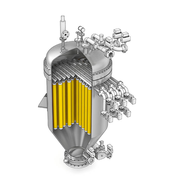
During operation, a feed pump or pressure from the reactor or feed tank forces the slurry into the bottom of the pressure vessel. The solids build up on the outside of the filter sock, while the liquid filtrate flows into the candle, through the registers, and out of the vessel. This process continues until the maximum pressure drop, design cake thickness, minimum flow, or maximum filtration time is reached. The cake is washed to remove impurities and residual mother liquor, and then dried by blowing gas through the cake. Next, low-pressure gas enters the individual candles or central dip tube and gently expands the filter socks. This process breaks apart the dry cake, which detaches from the filter sock and falls into the vessel cone. Candle filters are used for thin-cake (5–20 mm) pressure filtration applications. They are best suited for filter cakes that are vertically stable.
Circular pressure plate filter
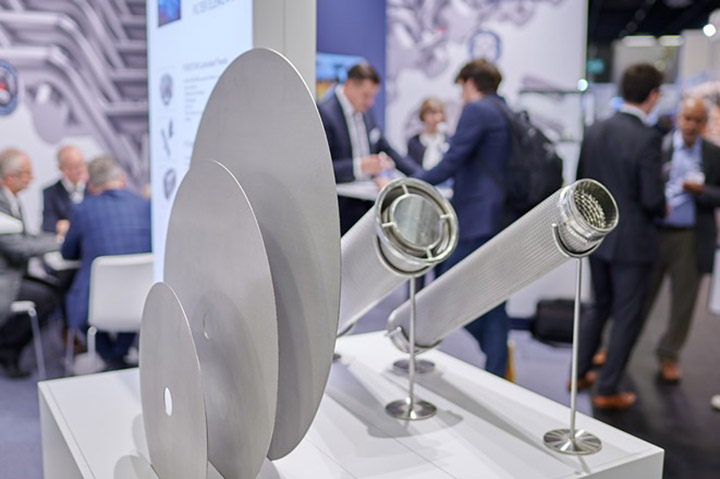
Like the candle filter, pressure plate filters (Figures 2 and 3) are comprised of filter plates contained within a pressure vessel. However, instead of vertical filter candles, the vessel contains circular-horizontal filter plates. These plates are conical-shaped slightly sloped, metal plates that support a coarse-mesh backing screen covered with filter cloth. An opening in the center of the plate allows the filtrate to travel between plates and out of the vessel. The filter cloth can be synthetic, as in the candle filter, or metallic as the cake discharge is by plate vibration or plate spinning.
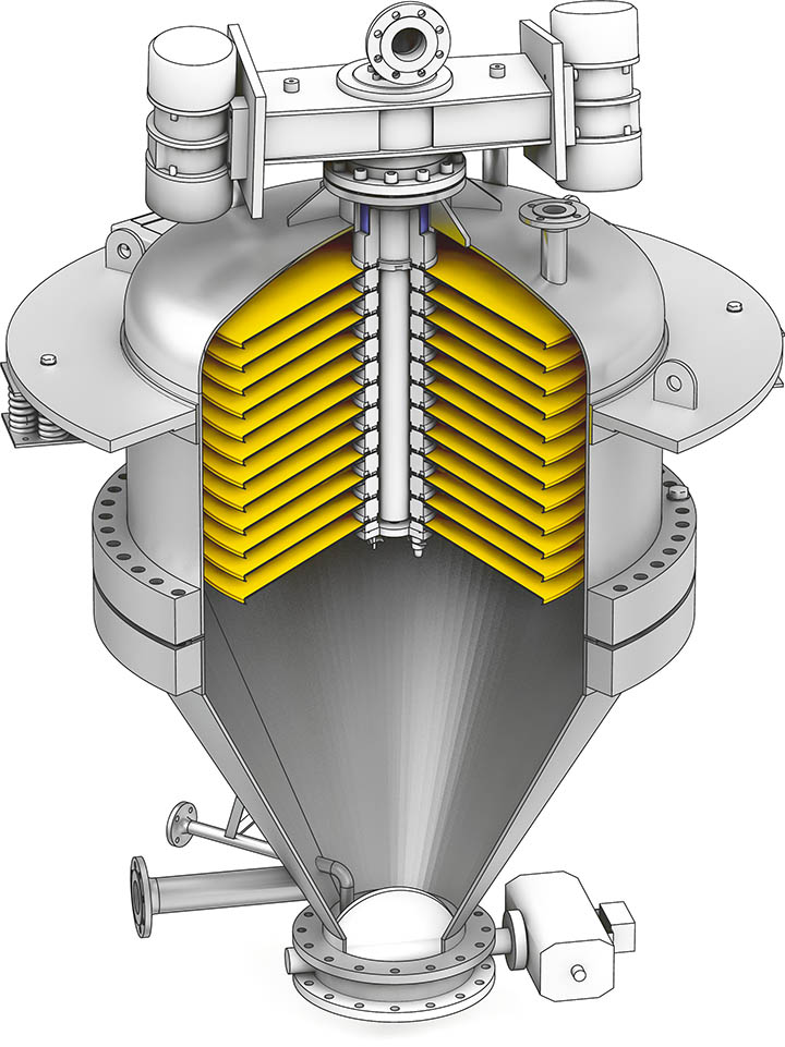
Operation is similar to that of a candle filter. The slurry enters the bottom of the vessel and is pumped upward. The solids build up between the plates, while the liquid flows through the core of the filter plates and exits from the top of the vessel. The cake is then washed and dried.
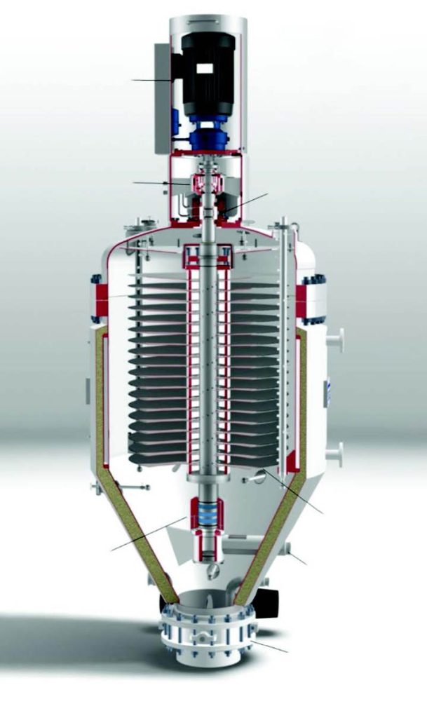
For cake discharge, there are two main designs. In one design, Figure 2, two unbalanced motors vibrate the filter plates to dislodge the cake from the filter cloth. In a second design, Figure 3, the plates spin so that the cake can be “thrown” off the plates. Pressure plate filters are used for filtration of cakes up to 75 mm thick. They are selected for cakes that are stable horizontally because of the orientation of the plates.
Cake structure and laboratory testing
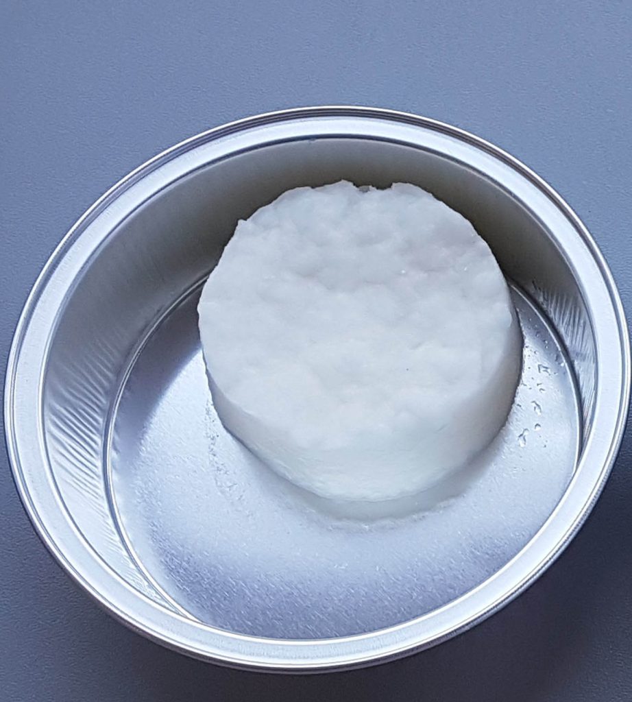
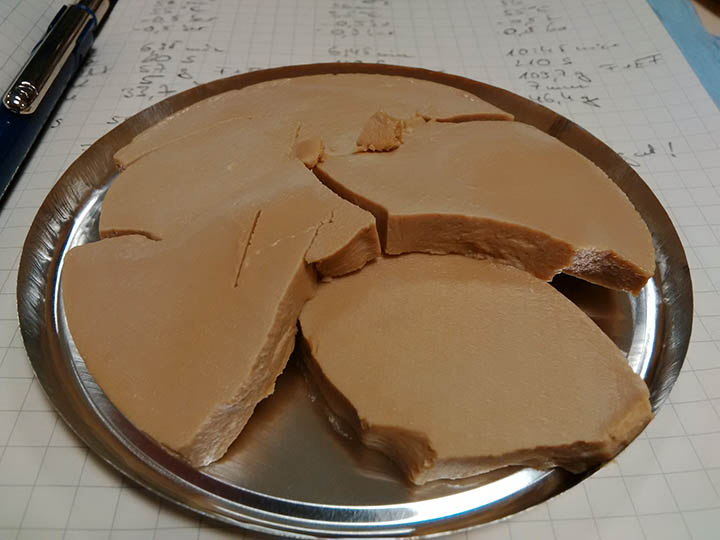
The structure of the cake determines which system is better suited for the application. Cakes comprised of crystalline or hard, irregularly shaped particles, which are stable and do not crack when oriented vertically and are compatible with the vertical filter elements of a candle filter. Alternatively, very fluffy or dense cakes are stable when horizontal and need to be handled by a circular plate filter. Figure 4 shows two examples of cake structures.
Laboratory testing at a constant slurry flow or constant pressure is used to determine the size and design of a clarification system as well as the cake structure by visual means. The tests evaluate the filter media, cake thickness operating pressure, cycle times, process parameters, quality and the use of filter aid to determine the optimum clarification system. Many vendors have lab test units or can conduct the bench-top testing in their own facilities.
Filter media
There are two main types of filter media – synthetic cloth and metal. Candle filters use synthetic cloth, while circular plate filters can use either synthetic or metal. The choice of media depends on the filtration removal efficiency, process requirements, filter technology, characteristics of the solids and liquids, cake release properties and other parameters. In terms of synthetic cloths, there are many choices including Polyester, Nylon, Polypropylene, PVDF (Kynar), PEEK, and Fluoropolymers (such as ETFE, PTFE, E-CTFE). For metal media, the material possibilities are stainless steels and alloys. After the lab testing, the technology supplier will be able to recommend the correct choice of filter media.
Filter aids
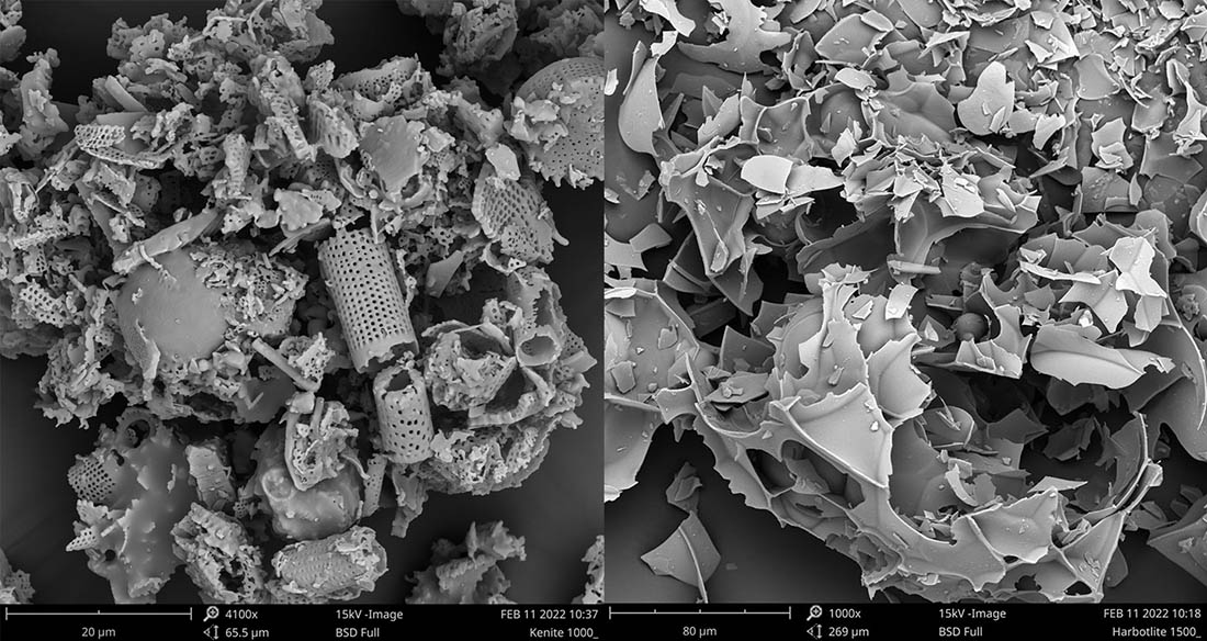
There is one final topic for clarification, which is the use of filter aid and is the last resort. Often in clarification applications, the solids are very fine or amorphous, which can be difficult to filter. When filtered, the solids will create a thin impermeable coating over the filter media and immediately reduce the filtration rate to an unacceptable level. In these difficult cases, filter aid pretreatment can be used to improve filtration properties and efficiently remove the fine solids from the process liquids. The two main types of filter aid are diatomite and perlite, as shown in Figure 5. The selection of the filter aid as well as the quantities are determined during testing. Finally, the filter aid can be used as a precoat or body feed, as described below.

Diatomite, also known as diatomaceous earth (DE), is comprised of the microscopic silica skeletons of prehistoric plants. This material is mined and calcined to destroy any organic matter and then milled and separated into various filter aid grades.
Perlite is formed from glasslike volcanic rock that consists of small particles with cracks that retain water and gas. The perlite is mined and transformed into filter aid by heating the ore to the melting temperature. Once the ore reaches the melting point, the molten volcanic glass expands and fractures due to the emission of the steam and gas. This expanded material is then crushed and classified to provide different filter aid grades.
In the precoat method, filter aid is used to generate a thin layer of solids on top of the filter media. Once formed, the filter aid cake functions as the primary filter media. Therefore, the filter cloth is no longer the real filter when precoat is used. For that reason, the filter cloth should be as open as possible while still retaining the filter aid material.
When confronted with a clarification process, the one thing not to do, is to repeat the solution with more bag filters, more filter aids and more throwaway cartridges. Take a different approach by conducting lab testing to analyze the cake structure, filter media, filtration pressure and cake thickness.
The precoat process is achieved by mixing the filter aid into clear liquid or mother filtrate in a precoat tank. This slurry is then recirculated through the filter where the solids are captured by the filter media. The clean filtrate is recirculated back into the precoat tank. The precoat thickness should be thick enough to ensure that the entire media surface is coated, but thin enough so that it does not provide significant resistance to filtration.
In body feed filtration applications, the filter aid is blended with the slurry feed either by dosing the concentrated filter aid suspension into the slurry feed with in-line mixing or by mixing the filter aid into the entire slurry batch and maintaining agitation. By adding filter aid into the slurry feed, the resulting filter cake is more porous, allowing higher and longer sustained flow rates. Body feed also helps to restrict solids movement, which improves filtrate clarity.
There are benefits and pitfalls of using filter aid, but this would be a topic for another article. Needless to say, the use of filter aid improves filtration but requires more equipment, more process control and results in more solids for disposal.
Final thoughts
How can the process engineer be successful to automate the clarification processes to improve filtration while minimizing operator exposure? Over my career in solid-liquid separation, there are interesting examples of how and how “not-to” solve a solid-liquid separation problem. In one case, in a resin facility, the slurry was in a formaldehyde process and the operators were wearing “masks” opening up a manual plate filter to dig out the cake. In another case, during the manufacturing of zeolites, the client had multiple bag filters to clarify the filtrates following a vacuum belt filter. When the filtrates, the final product, remained cloudy, surprisingly, the client decided to add another set of bag filters. There are many examples of process engineers struggling to clarify process liquids.
When confronted with a clarification process, the one thing not to do, is to repeat the solution with more bag filters, more filter aids and more throwaway cartridges. Take a different approach by conducting lab testing to analyze the cake structure, filter media, filtration pressure and cake thickness. There are many resources to do this work from vendors, consultants and published literature. With the data in hand, the different technologies discussed above can be evaluated for a reliable and cost-effective clarification process.


