The difference between a filter and a separator is that they are used in the liquid/solid industry, particularly with applications using industrial process fluids. These applications have a continuous input of solids that are regularly removed on a closed-loop basis as the fluid is recirculated through the cleaning device and back to the operation. They are commonly known as metalworking/coolant applications.
This article focuses on manufacturing parts made of steel or ferrous materials. It does not cover manufactured parts made of nonferrous materials.
Although the discussion is devoted to industrial metalworking applications, there are many applications in other industries where separators are used to remove solids from liquids. This article describes the separator in more detail since it is not as well-known as a filter. In fact, many users still refer to a separator as a filter because, in their experience, anything that cleans a fluid is a filter. This article shows the difference between the two.
Difference between Filters and Separators
First, the definitions of the two devices are provided to show the actual difference between them. For this discussion, a filter and separator are types of clarifiers. They belong here because they clean contaminated liquids, but their techniques for accomplishing this task are different.
Filter
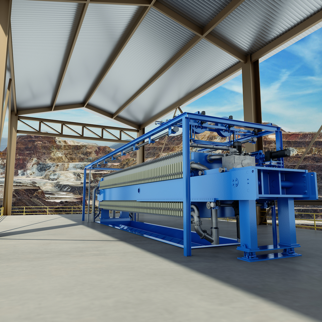
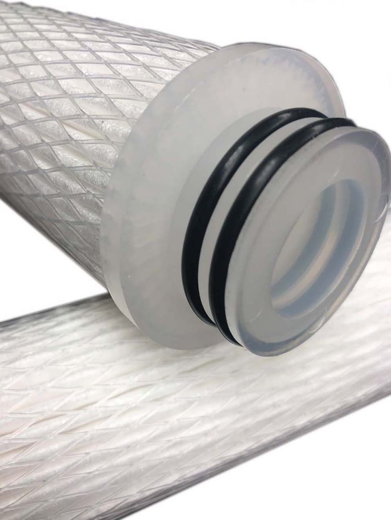
A filter uses a barrier to intercept the solids as the liquid flows through it. Particle size and particle size distribution are the main parameters. It is common knowledge that many types and fabrics are available. There are many types of filters which use a media in many design arrangements.
Separator
A separator uses the physical characteristics of the solid and how they relate to the physical characteristics of the liquid. It capitalizes on the differences to “pull,” remove, or separate the solids away from the liquid. It cleans the liquid without the use of a barrier or filter medium to intercept the solids.
Typical characteristics of these are;
- Solids heavier than liquid – they settle to the bottom of a tank to be removed manually or with a sludge conveyor.
- Solids lighter than liquid float to the surface of the tank and are removed with a skimmer of some type. This is not common with ferrous material.
- Magnetic particles – can be separated with a magnetic field magnetic created by drums, discs or curtains.
Solids can be forced into an accelerated separation with centrifugal force generated by centrifugation with a centrifuge or a hydrocyclone.
There are separators that work as liquid/liquid separators, such as tramp oil or foreign liquids. These use flotation and skimming. In some unique cases, vacuum distillation can be used. However, these are not covered here since the main theme is liquid/solid separation.
Examples of Typical Liquid/Solid Separators
The following illustrations show some typical separators used in the industry. Of course, there are many types and variations of each. Space will not allow the insertion of all of them. Therefore, the following are the most common devices. Each device has a brief description covering the most salient points of its
design or application. There is much more data than what is offered here, so a user should learn as much as possible about the device’s design and features before making a selection. Each device has many versions of the basic design, and often, they can be modified to meet the cleaning needs better.
Self-Cleaning Settling Chamber
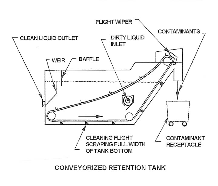
A typical self-cleaning tank (there are many types) has a flight or scraper, which is pulled along the bottom and up an incline to discharge the contaminants into a suitable receptacle. The figure shows a typical arrangement where the device takes advantage of the solids being heavier than the liquid. The flight mechanism has various designs. They usually run continuously at a slow speed and at a rate required to remove the necessary solids. The speed of the conveyor is between one foot to ten feet per minute. It is wise that whenever the tank is selected to hold contaminated fluid long enough to where the solids will settle to the bottom, the tank should be fitted with a self-cleaning conveyor. Otherwise, manual cleaning is needed frequently. If the manual cleaning is ignored, the solid accumulation actually displaces the liquid and the system is starved of valuable fluid.
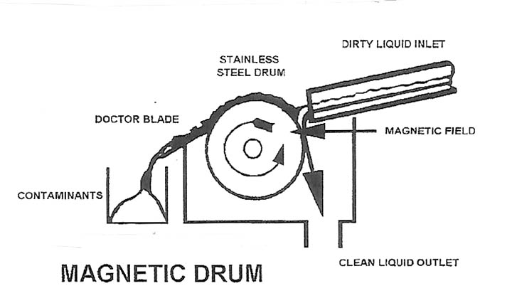
Magnetic Drums
Magnetic separation takes advantage of the magnetic characteristic of steel/ferrous contaminants. This magnetic drum separator has a stainless steel drum rotating over a magnet field. The magnetic field is in the path of the liquid flow to attract the particulate and hold it as the fluid flows by. These units use doctor blades or wipers to scrap away the accumulation of particles. There are many configurations of the drum version, and they are often used with system reservoirs.
Magnetic separation can be performed with many types of devices which hold a magnetic field in the path of the moving liquid. Some are designed as conveyors as in chip conveyors under a machine which is cutting the metal.
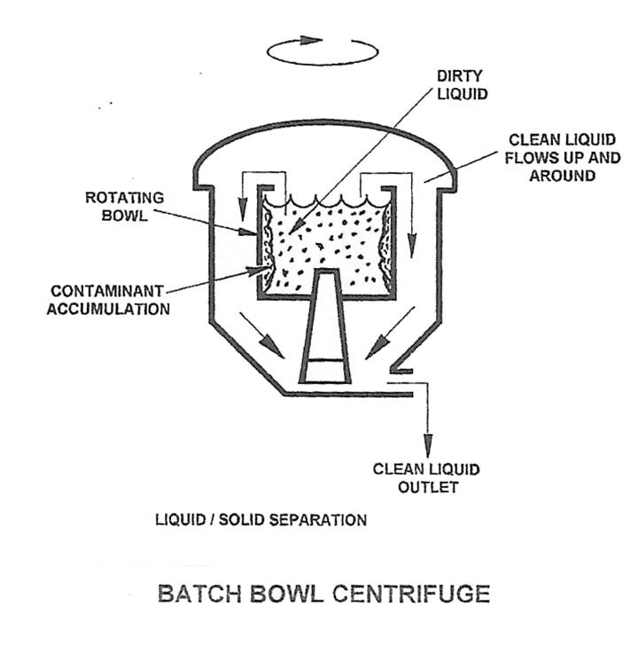
Batch Centrifuge
This shows a liquid/solid separating batch bowl centrifuge containing dirty liquid inside a rotating bowl. As the bowl spins, the centrifugal force pulls the solids toward the wall. The liquid is also pulled but It flows over the top edge of the bowl and down into the bottom of the chamber and out the clean liquid outlet. Solids are accumulated on the inside surface of the bowl. After the required time, the centrifuge is shut down, opened, and the solid mass in varying degrees of “dryness” is manually removed.
There are three main types of centrifuges: Batch, as shown here, Continuous Flow, where the fluid continuously flows in and out of the chamber, and Stacked Disc, high-speed centrifuge. The stacked disc is usually designed to be self-cleaning and is the most efficient device in the family of separators. For all the units, the rotating speed ranges from 2,000 RPM to 10,000 RPM. Higher speeds are usually found in high-speed stacked disc units. Batch systems are more dependent on operator attention since they require manual cleaning.
Hydrocyclone
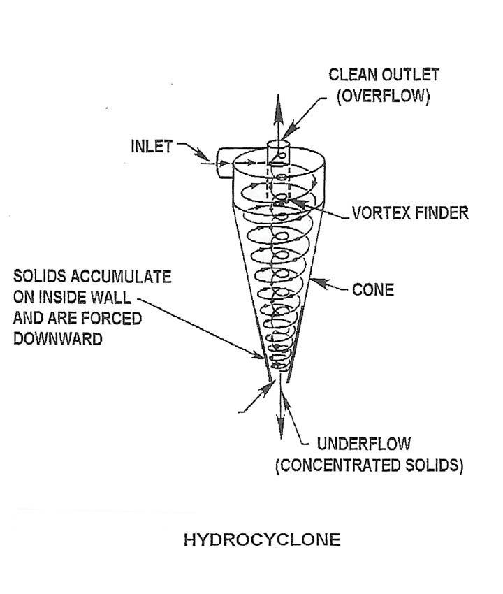
Centrifugal force is the hydrocyclone’s method of separating the solids from the liquid. This is different from a centrifuge since the forces are generated inside the stationary conical chamber as the liquid spins at high velocities; the inlet is at a tangent to start the spinning action. As the liquid flows downward, the gradual reduction in the cone’s diameter greatly increases centrifugal action and the solids or heavier material is pushed to the inner wall of the cone. The opening at the bottom is not large enough to allow all the liquid to flow out the bottom. The center column of liquid is cleaned and it “swells” upward out the top of the unit. This is called the overflow. The liquid escaping out the bottom carries the concentration of solids. This is called the underflow. In industrial applications, the hydrocyclone is effective with granular type of solids. There is hardly any success with flake-like particulate. The velocity buoys the flakes and can be easily carried out the clean outlet at the top. The flakes tend to plug the bottom underflow outlet and prevent the hydrocyclone from functioning properly. The Hydrocyclone is mainly used on water base fluids.


