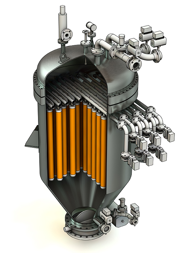
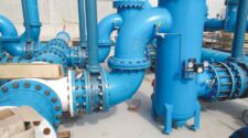
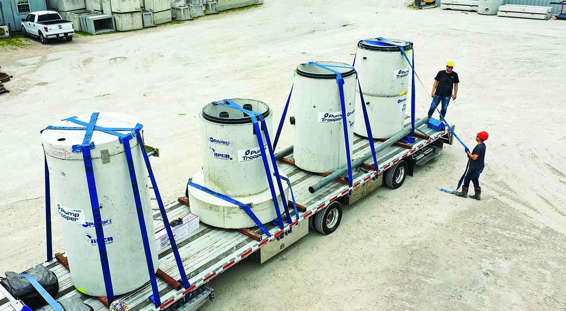
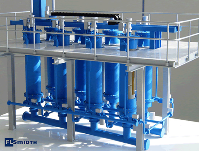
Figure 1: BHS Candle Filter Technology
Treating water for environmental and process benefits is becoming more important in the oil and gas, energy, bioenergy, biochemical and chemical industries. As these operations are looking to become more cost efficient, water usage is being investigated. One critical aspect of these processes is the solid-liquid separation technology that is used to keep the water free of solid contaminant fines.
This paper discusses thin-cake candle filter technology as an alternative to filter presses and bag and filter cartridges for removing solid contaminant fines from the water streams. These contaminants originate from various sources and are generally less than 1 micron (um) in size, which makes their removal very difficult. Candle filter technology and the process of thin-cake building, is a new approach for high-efficiency and cost-effective fines removal.
The paper begins with the problem definition and a discussion of the bench-top laboratory tests that are conducted for problem analysis, process development, technology selection and scale-up. The tests include pressure, filter media, filter aids, and similar process parameters. The candle filter technology is examined for its ability to filter and dry the contaminants to meet the standards of non-hazardous and “no free liquid” for solids disposal. Cake washing is also discussed, as, in some cases, soluble or insoluble components or hazardous solvents must be removed from the solid cake prior to disposal. Three different case histories are presented for purge water treatment units using filter aids, concentration without filter aid, and grey water concentration. Finally, there is a discussion of the impacts of chemical usage in clarifiers on filtration efficiency and troubleshooting.
Introduction
Water usage has many applications at refineries, gas plants, chemical plants and bioenergy /biochemical facilities. Wet scrubbing at refineries, for example, reduce sulfur dioxide (SO2/ SO3) and are the primary and fine particle removal mechanisms from the flue gas. In gasification, water carries the coal fines and catalyst fines during the process. Clarifiers are used in many applications to settle/concentrate to sludge and remove the solids from the process. While the plant location and type of removal process may vary, there is a need to remove the fine particulate matter from the water streams for either reuse or disposal. The particulate matter can be catalyst fines and other contaminants in the feedstock. It is difficult or impossible to remove particles of this size in settling tanks, hydrocyclones or centrifuges, so the particles must be removed by pressure filtration. The use of thin-cake candle filter technology has been proven to be a cost-effective and reliable approach for removing the contaminants, recovering the scrubbing liquids and drying the cake for non-hazardous and “no free liquid” landfill disposal.
Problem Definition
Various catalyst, corrosion products and carbonized particles are carried into the gas and are captured by the water with flow rates as high as 200 m3/hr. The fine particles are less than 1 micron and can be up to 1% solids in the slurry. Bag and filter cartridges at these solids concentrations are uneconomical and could result in costs of over $500,000 per year. Similarly, the use of filter presses has high operating and maintenance costs. This paper discusses specifically the removal of these fines and provides three illustrative case histories.
Technology of clarification & recovery of solids from slurries
Candle Filters are installed for clarification and recovery applications from liquids with low solids content. They provide clean fluids to 0.5 micron with either a dried cake (no free liquids) or concentrated slurry.
Candle filtration technology
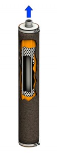
A candle filter is a pressure vessel filled with tubular filters called filter candles (Figure 1). A typical filter candle is comprised of a dip pipe for the filtrate and pressurized gas, a perforated core with supporting tie rods,
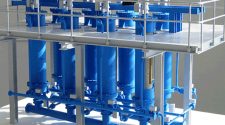
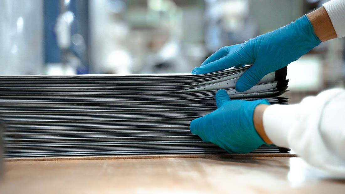
and a filter sock (Figure 2). The filtrate dip pipe runs the length of the candle and ensures high liquid flow, as well as maximum distribution of the gas during cake discharge. The tie rods create an annular space between the filter sock and the perforated core, which helps to maintain a low-pressure drop during operation and promotes efficient expansion of the filter sock during cake discharge. The filter sock is installed over the candle, and can be made of various synthetic materials, capable of removing particles smaller than 1 ╬╝m. As the cake builds during operation, the candle filter’s removal efficiency increases, enabling removal of particles as small as approximately 0.5 ╬╝m.
The candles are installed in a pressure vessel constructed of stainless steel or another alloy. Within the vessel are horizontal manifolds called candle registers. Each candle is connected to a register with a positive seal to prevent bypass. Depending on the filter size, each register may contain 1-20 candles and the total candles can be over 200 candles per vessel. The liquid
filtrate and pressurized gas flow through the register; automated valves ensure optimum flow in both directions.
Discharge
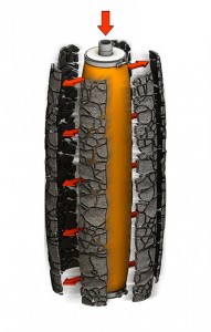
During operation, a feed pump forces the slurry into the bottom of the pressure vessel. The solids build up on the outside of the filter sock, while the liquid filtrate flows into the candle, through the registers, and out of the vessel. This process continues until the maximum pressure drop, design cake thickness, minimum flow, or maximum filtration time is reached.
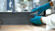
The cake is washed to remove impurities and residual mother liquor, and then dried. Next, low-pressure gas enters the individual candles and expands the filter socks. This process breaks apart the dry cake, which detaches from the filter sock (Figure 3) and falls into the vessel cone. The cake can also be discharged as concentrated slurry without drying.
Candle filters are used for thin-cake (5-20 mm) pressure filtration applications. They are best suited for filter cakes that are vertically stable because of the orientation of the candles.
Determining candle filter system design
Laboratory testing at a constant slurry flow is used to determine the size and design of a clarification system for processes with extremely low concentrations of solids. The test evaluates the filter media, operating pressure, and cake thickness to determine the optimum clarification system design and size.
A lab-scale leaf filter is used as the test filter. Various filter media can be installed, depending on the desired filtrate clarity, filtration flux rate (time), cake thickness, and cake discharge rate, as well as compatibility with the process. A peristaltic pump supplies a constant flow of slurry to the filter, and a pressure gage measures the change in pressure (delta P) across the filter media.
The washing analysis consists of running a liquid at the same or different flow rate as the test flow rate through the peristaltic pump, or adding wash liquid to the leaf filter directly and applying air or gas (nitrogen, argon, etc.) pressure until the target pressure drop or quality (conductivity, acid level, etc.) is reached.
The cake is then dried with pressurized gas or air. The amount of compressed gas is regulated to prevent the use of excess gas, which could lead to overly optimistic moisture targets and uneconomical compressed gas volumes when scaled up.
Water scrubbing and clarifier effluent using filter aids: Alternative to filter cartridges
In this application, a wet scrubber is used to remove catalyst fines and sulfur dioxide from a fluid catalytic cracking unit flue gas. A purge stream is sent from the wet scrubbing system to a purge water treatment unit and then to disposal. The candle filter system removes catalyst particles fines from the clarifier effluent stream prior to discharge. The flow rate is 70 m3/hour with a solids concentration of 190 ppm. The particle size is below 0.5 micron down to 0.06 micron. The filtrate specification for discharge is less than 40 ppm. Initially, filter cartridges were planned but the cost of change out alone, based upon the above parameters was estimated to be over several million dollars not including the cost of cartridge inventory, disposal and manpower for cartridge change out, assumed to be every shift.
BHS conducted laboratory tests, as previously described including the use of filter aids due to the size of the particles being less than 0.5 microns. The installation consists of two BHS candle filters, each with 100 m2 of filter area and a filter aid pre-coat package.
Water scrubbing-clarifier effluent concentrating without filter aids: Alternative to backwashable metal cartridges
In this application, the wet scrubber water purge is pumped to a clarifier for primary removal of large catalyst solids. The clarifier overflow discharges to an oxidation tower and the effluent from the tower is pumped through the effluent filter and heat exchanger prior to discharge.
The flow rate is 46 m3/hour with a solids concentration of 200 ppm. The particle size is below 1.0 micron. The filtrate specification for discharge is less than 15 ppm. Initially, back washable metal cartridges were planned but the low dirt holding capacity of the metal cartridges and the frequent backwash, which is sent back to the clarifier, was estimated to be uneconomical. Therefore, the decision was to look at the BHS candle filter technology solution.
As this process required concentrated slurry rather than a dried cake, the BHS process solution was concentrating candle filters without filter aid. The installation consists of two BHS candle filters, each with 25 m2 of filter area. The benefits of the candle filter solution included clear filtrates to less than 1 ppm as well as less backwash to the clarifier as the candles are “cleaned” with compressed gas and not liquid.
Grey water concentrating
In this application, grey water containing catalyst fines, coal fines, char and other non-reactive solids required clarification to 0.5 microns. The filtered water is sent back to the gasifier process while the solids are sent to the wastewater plant. The grey water flow rate is 180 m3/hour with a solids concentration of 200 ppm.
BHS conducted lab testing to determine the filtration flux rate. It was also determined that due to the flow rate and low solids, it was a more cost-efficient approach to do the final solids drying in a filter press rather than on the candle filters. The concentrating candle filters produced a clear filtrate of 0.5 microns as well as reduced the feed to the wastewater plant to 10% solids at 300 gallons every 2 hours compared with 800 gpm at 200 ppm.
Filtration system troubleshooting
There are normally three main areas that must be examined when the filtration system appears not to be functioning properly. These areas include: (1) the filter itself for mechanical reasons, (2) the equipment around the filter is not working and (3) the filter operational procedures are not correct. Let’s examine these groups but more importantly, it is necessary to separate the symptoms from the causes. As will be seen, excessive solids in the filtrate (the symptom) have many causes (damaged filter cloth, PSD changes from the reactor, post-precipitation due to temperature changes, etc.).
First, there could be a failure of the equipment itself such as internal components, seals, etc., all as is normally described in the O & M preventative maintenance section from the supplier. This should be the first item to be checked.
Secondly, the filtration system is part of the entire process including the upstream and downstream equipment. For example, are the reactors performing correctly in terms of agitation, temperature control, etc. in order to produce the specified crystals? Are the filter aid systems in tune for mixing, feeding, flow rates, solids loading, etc.? Are the valves and instruments operating correctly and reading the correct variables (calibrations), etc.? Next, what about the pumps that feed the slurry and washing liquids as well as the compressors that feed the gas streams for drying and cake discharge. Finally, are their interlocks in the control system or a control communication problem that are not being recognized that are causing the filter problem?
Finally, there may be process or operational procedures that are resulting in filtration problems. For example, the particle sizes may have changed, the amount of solids in the slurry may have changed, the cake compressibility may have changed, etc. In terms of the operation, has the filtration pressure changes timer changed, speed changed, etc.?
Troubleshooting the water scrubbing-clarifier effluent concentrating system
In a clarification application previously discussed, the system was installed and started up and successfully ran for over one year. Inexplicitly, the performance changed drastically and the filter media began plugging very quickly during the cycles. The process engineers explained that there had been no change in the process and began to investigate the upstream conditions using the list below.
A. Clarifier overflow with no coagulant / no flocculants
B. Clarifier overflow with only coagulant / no flocculants
C. Clarifier overflow with both coagulant and flocculants
D. Clarifier overflow with only flocculants / no coagulant
After months of work, the process engineers narrowed down the changes to the chemical supplier of the flocculants and coagulants. BHS and the client began lab testing again using the initial slurry along with the chemical supplier and their flocculants and coagulants. The resulting testing showed that the chemical change caused the larger particles to settle out quickly and therefore only the smaller particles reached the filtration system, which was blinding the filter media. The client and the chemical company eliminated the flocculants and reduced the amount of coagulant used (better for the client and not so good for the chemical supplier), which produced a smooth and consistent particle size distribution and better filtration rates. Once again, we see the systems and holistic approach to process filtration.
Summary
Sherlock Holmes and Dr. John Watson are fictional characters of Sir Arthur Conan Doyle. Process engineers who live in the real world can learn many things from the two of them for solving process filtration problems. One example that Holmes proves time and again is that there is no benefit to “jumping to conclusions.” As discussed in the illustrations, there are many choices of filtration technologies to achieve the necessary level of quality with a cost-effective and a reliable process. Also, in terms of troubleshooting, there are many causes of filtration symptoms. With careful analysis and taking a creative and “non-conventional approach” by looking at what is behind the process data and the operating parameters, the optimum solution will be realized.


